目录
Arduino是一个开源的,支持多种类型单片机开发的代码框架,该框架最大程度的封装了Arduino开发板底层代码,开发者可以使用C++代码进行程序编写而不必思考底层(寄存器,时钟,外设等........)的实现,Arduino同时具有非常丰富和优质的库支持,非常适合没有硬件基础的软件开发者和想学习入门单片机开发的新手使用。
文档博客:https://misishijie.com/crankymonkey/arduino/arduino_overview.htm
第一个项目:点灯
环境准备:
1.Arduino IDE
2.开发板 Arduino UNO R4(WiFi)。
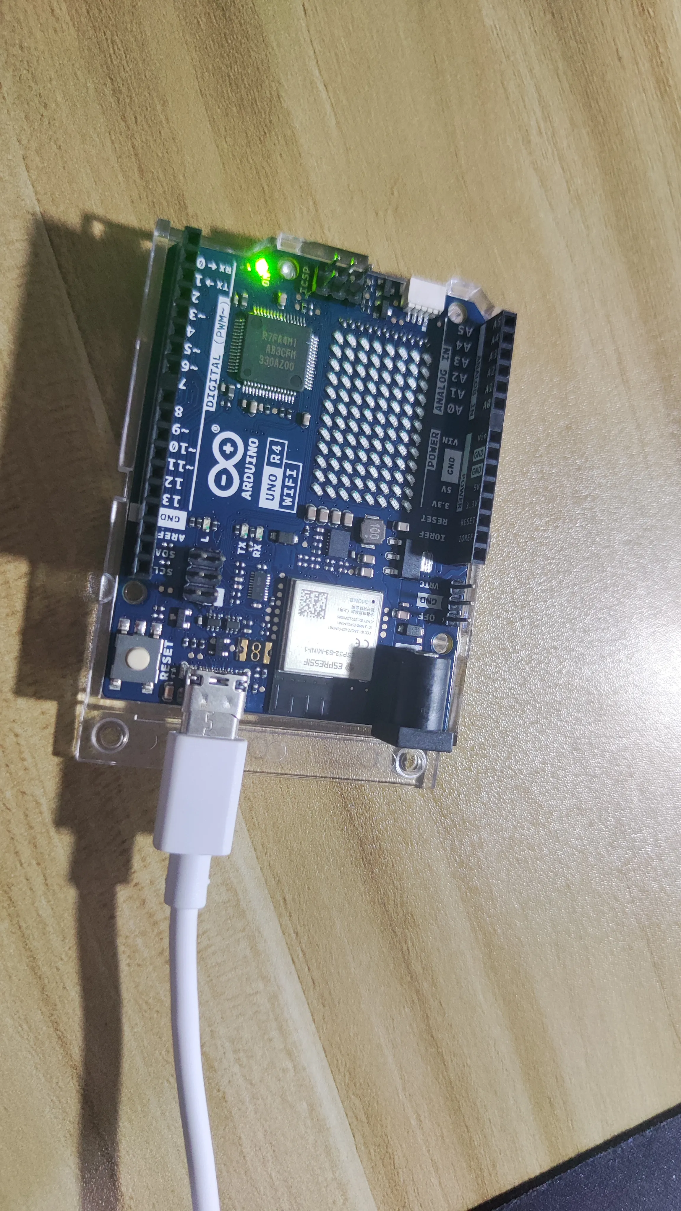
准备工作:
USB连接到开发板,打开IDE,安装开发板相关的库,在IDE里面选自己的设备(IDE会自动识别)
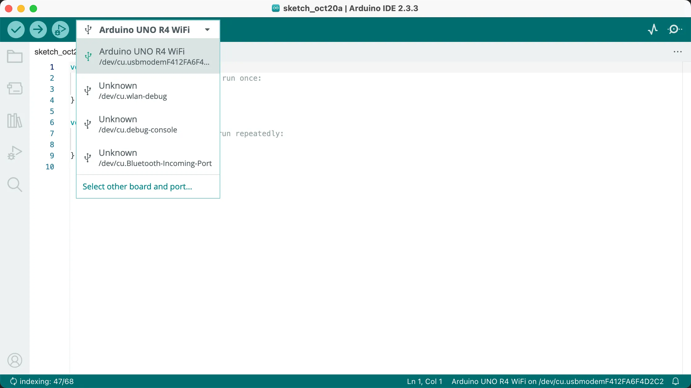
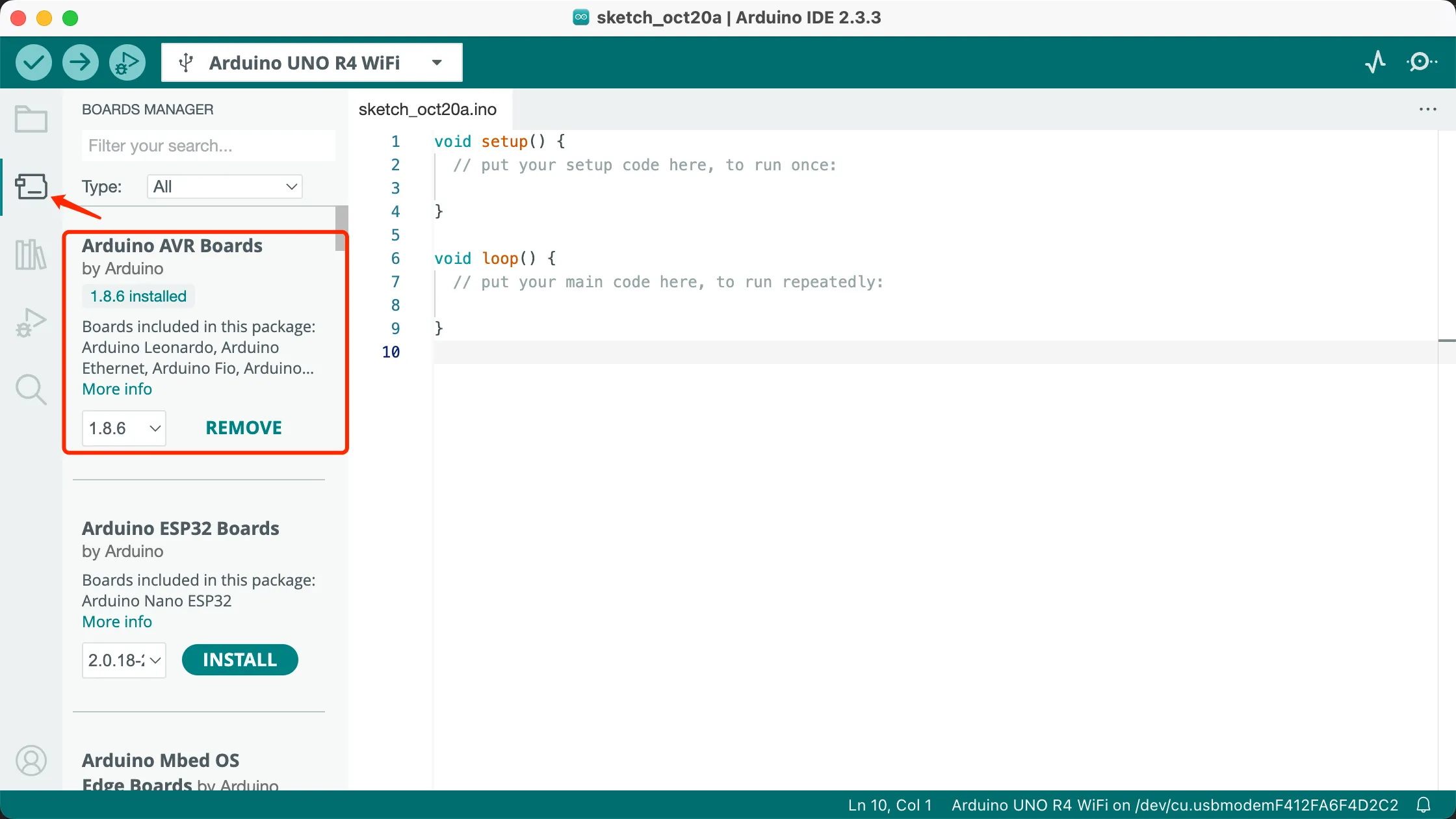
开始第一个程序:
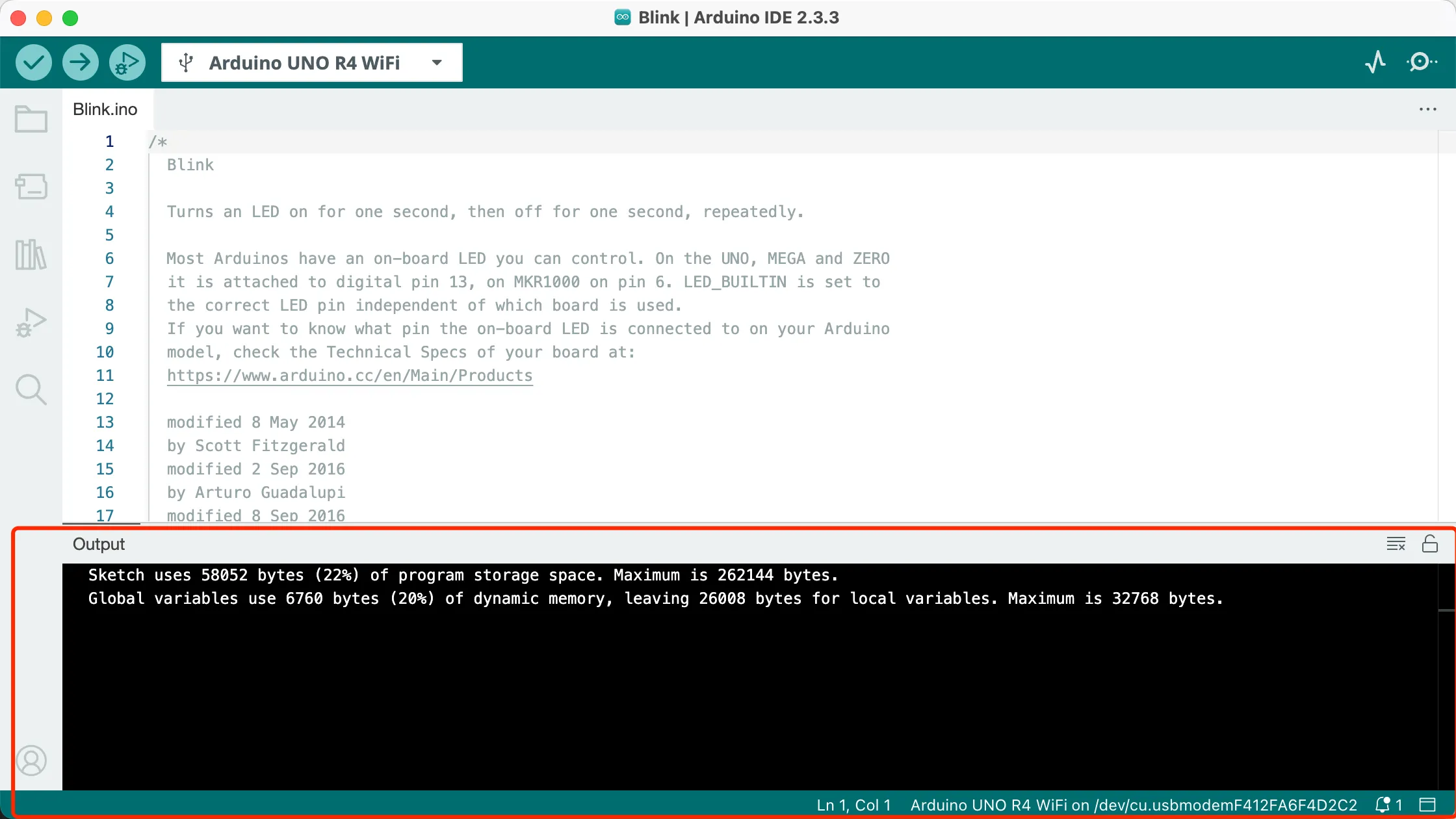
导入IDE的示例,找到File->Examples->01.Basices->Blink 然后开始编译:
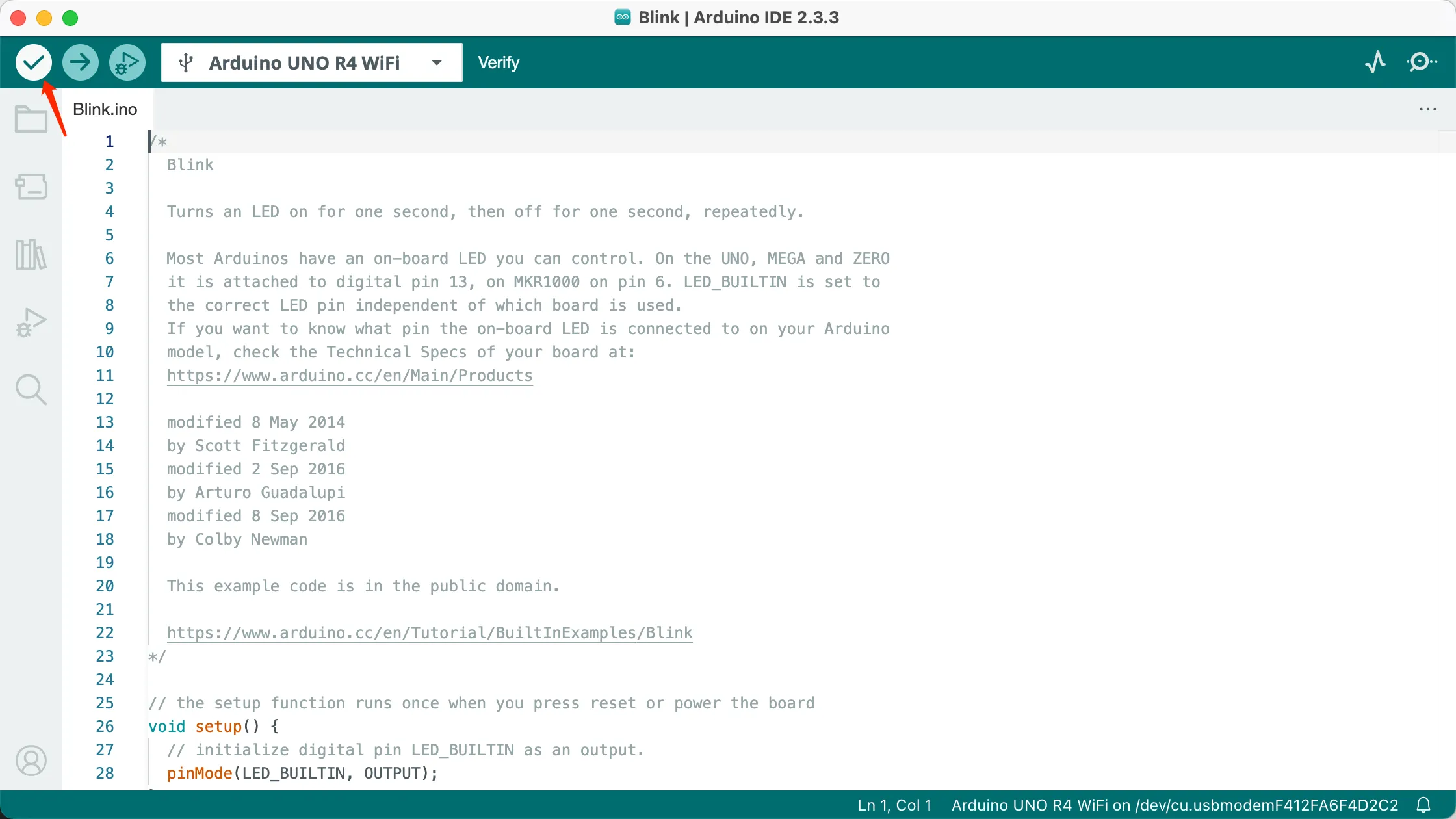 编译完成:
编译完成:
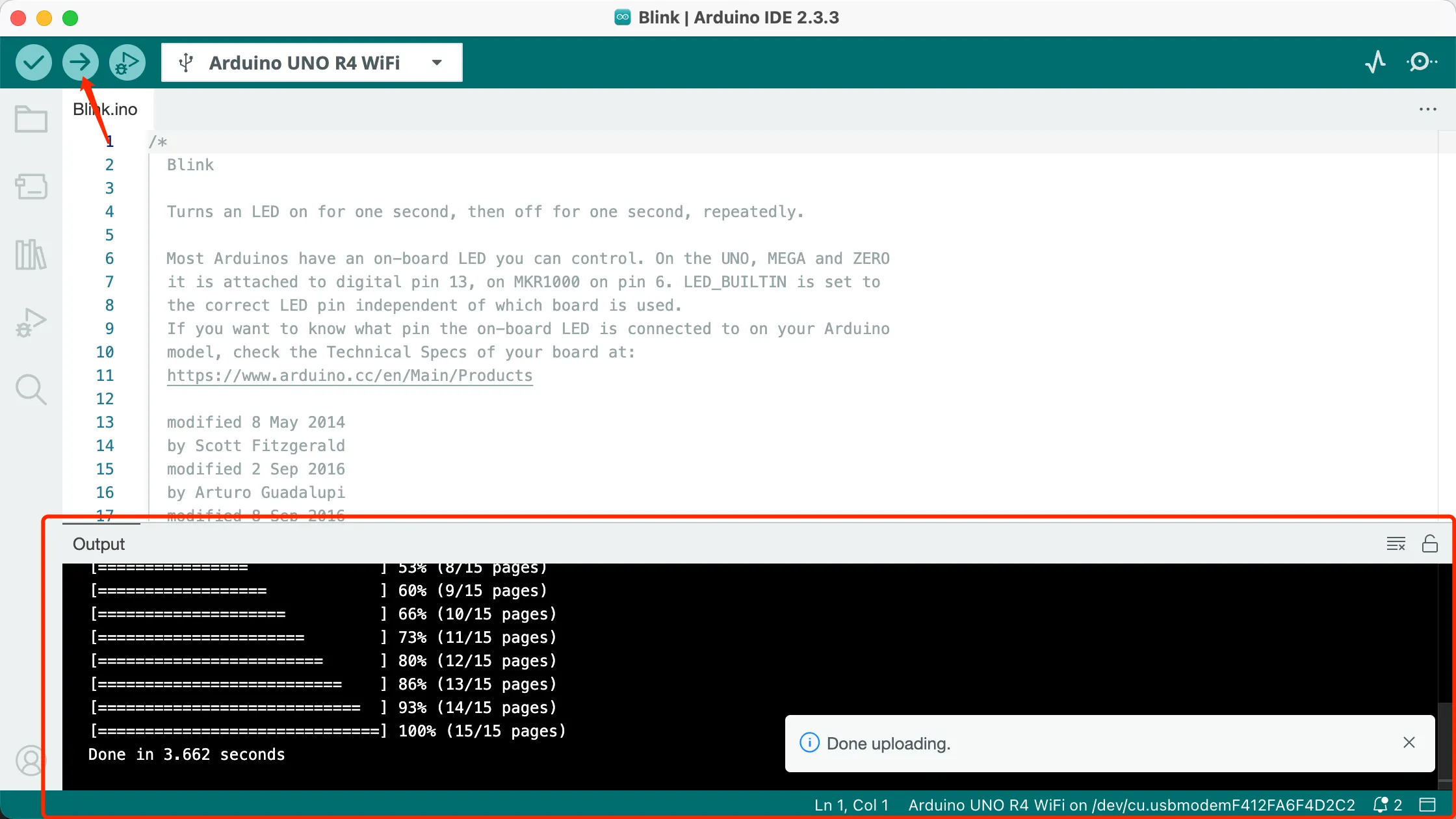
烧录程序到开发板:
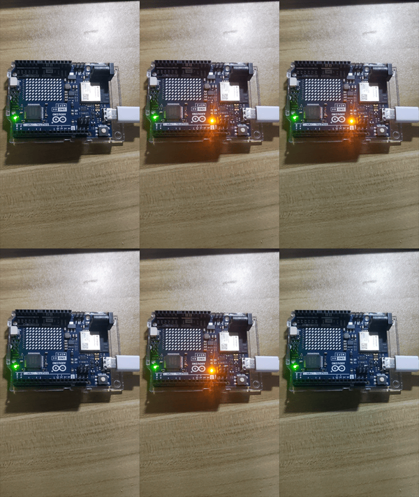
这时候应该能看到指示灯闪烁。
安装FreeRTOS
什么是FreeRTOS?
FreeRTOS,简而言之,就是一个实时操作系统,那么为什么需要操作系统? 不难看出,Arduino程序结构由setup()和loop()两部分组成,要反复执行的代码要放在loop()中,并且这些代码一般都是顺序执行的。当需要实现的功能越来越复杂时,这种顺序执行的方式很难达到实时性,也就是不能同时处理多任务。而FreeRTOS可以让Arduino程序同时进行多任务调度。
安装Arduino FreeRTOS库
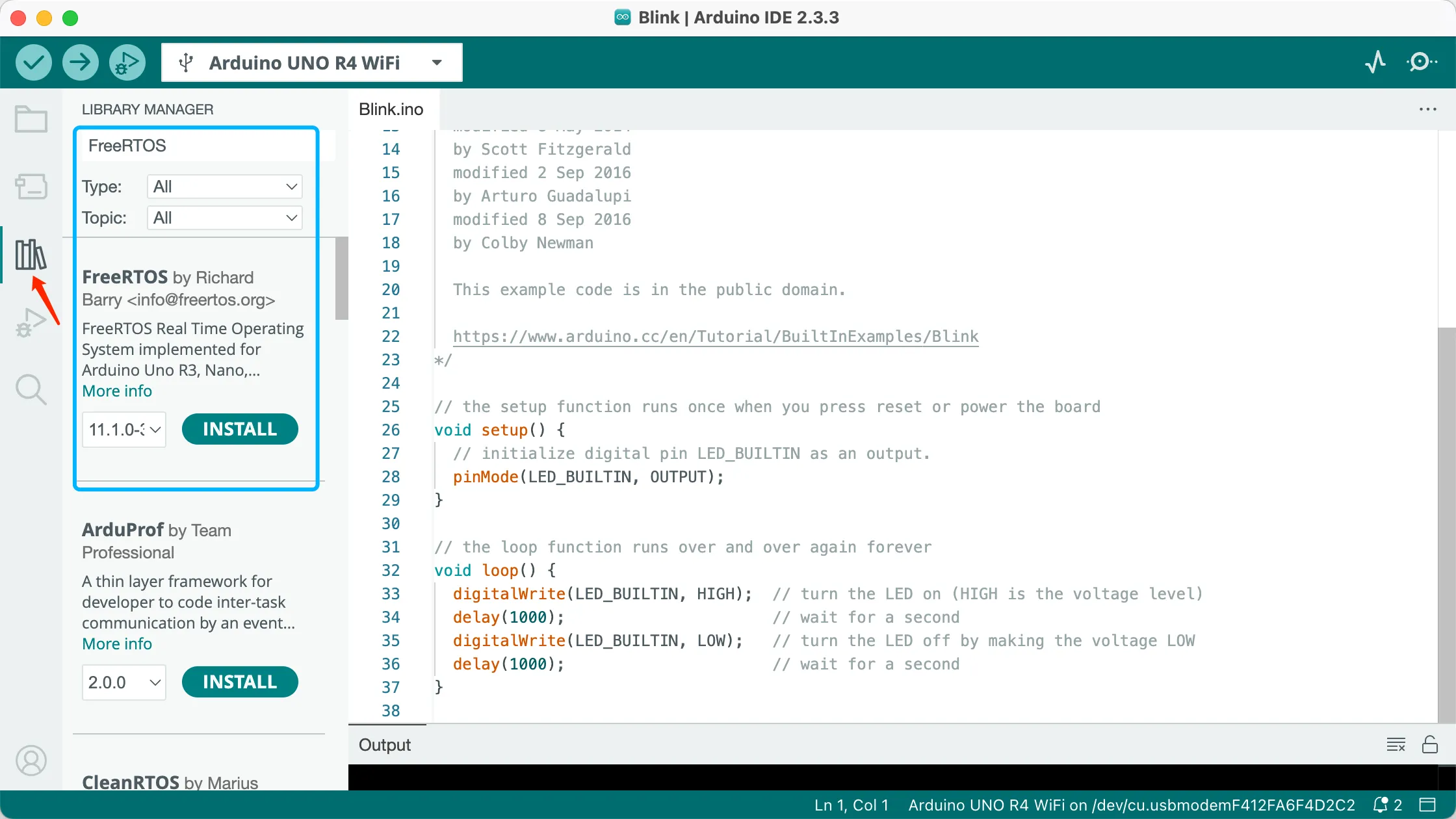
安装Arduino FreeRTOS快速上手: 首先要包含Arduino FreeRTOS库的头文件。
C++#include <Arduino_FreeRTOS.h>
我们使用xTaskCreate()函数来创建任务,函数原型为:
C++xTaskCreate(TaskFunction_t pvTaskCode,const char * const pcName,uint16_t usStackDepth,void * pvParameters,UBaseType_t uxPriority,TaskHandle_t * pxCreatedTask)
在创建任务时,需要传入以下6个参数:
- pvTaskCode:
- 说明: 任务函数的指针。
- 用途: 定义任务的执行代码。
- pcName:
- 说明: 任务名称字符串。
- 用途: 一般用于调试和追踪,以便在系统中识别任务。
- usStackDepth:
- 说明: 任务堆栈深度。
- 用途: 指定堆栈可以容纳的字数,而不是字节数。
- 示例: 如果堆栈为32位宽,并且
usStackDepth为100,则分配400字节的堆栈空间(100 * 4字节)。
- pvParameters:
- 说明: 任务输入参数。
- 用途: 可用于向任务传递数据,可以为NULL。
- uxPriority:
- 说明: 任务优先级。
- 用途: 设定任务的执行优先级,其中0为最低优先级。
- pxCreatedTask:
- 说明: 可用于接收任务句柄的指针。
- 用途: 允许在后续API调用中引用该任务,例如更改任务优先级或删除任务,可以为NULL。
创建两个串口任务和点灯任务:
C++xTaskCreate(taskPrint1, "Print1", 128, NULL, 1, NULL);
xTaskCreate(taskPrint2, "Print2", 128, NULL, 2, NULL);
xTaskCreate(blink, "Blink", 128, NULL, 3, NULL);
注意:在RTOS中,不建议使用 delay() 函数,因为它会停止CPU,因此RTOS也将停止工作。 FreeRTOS具有内核API,可以在特定时间内阻止任务:
C++vTaskDelay(const TickType_t xTicksToDelay)
例如延时1秒:
C++vTaskDelay(1000 / portTICK_PERIOD_MS)
其中portTICK_PERIOD_MS与实际MCU的时钟频率相关。
启动任务:
C++vTaskStartScheduler();
完整代码:
C++/*
  Blink

  Turns an LED on for one second, then off for one second, repeatedly.

  Most Arduinos have an on-board LED you can control. On the UNO, MEGA and ZERO
  it is attached to digital pin 13, on MKR1000 on pin 6. LED_BUILTIN is set to
  the correct LED pin independent of which board is used.
  If you want to know what pin the on-board LED is connected to on your Arduino
  model, check the Technical Specs of your board at:
  https://www.arduino.cc/en/Main/Products

  modified 8 May 2014
  by Scott Fitzgerald
  modified 2 Sep 2016
  by Arturo Guadalupi
  modified 8 Sep 2016
  by Colby Newman

  This example code is in the public domain.

  https://www.arduino.cc/en/Tutorial/BuiltInExamples/Blink
*/


#include <Arduino_FreeRTOS.h>


// the setup function runs once when you press reset or power the board
void setup() {
  Serial.begin(115200);           // Initialize serial communication at a baud rate of 115200
  // initialize digital pin LED_BUILTIN as an output.
  pinMode(LED_BUILTIN, OUTPUT);
  // Create task
  xTaskCreate(taskPrint1, "Print1", 128, NULL, 1, NULL);
  xTaskCreate(taskPrint2, "Print2", 128, NULL, 2, NULL);
  xTaskCreate(taskBlink, "Blink", 128, NULL, 3, NULL);
  vTaskStartScheduler();
}
void taskPrint1(void *param){
  while (1)
  {
    Serial.println("taskPrint1...");
    vTaskDelay(1000 / portTICK_PERIOD_MS );
  }
}
void taskPrint2(void *param){
    while (1)
  {
    Serial.println("taskPrint2...");
    vTaskDelay(1000 / portTICK_PERIOD_MS );
  }
}
void taskBlink(void *param){
    while (1)
  {
    digitalWrite(LED_BUILTIN, HIGH);  // turn the LED on (HIGH is the voltage level)
    vTaskDelay(1000 / portTICK_PERIOD_MS );
    digitalWrite(LED_BUILTIN, LOW);   // turn the LED off by making the voltage LOW
    vTaskDelay(1000 / portTICK_PERIOD_MS );
  }

}
// the loop function runs over and over again forever
void loop() {

}
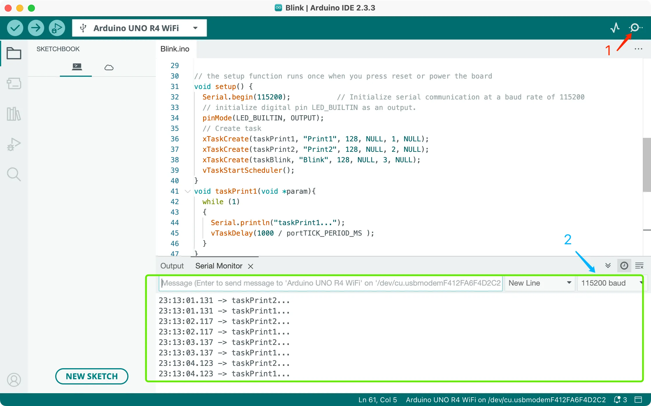
然后编译,烧录,再点开串口监视器,选择115200的波特率。 可以看到,两个打印任务正常,灯也正常闪烁。
Arduino IDE 多文件开发
Arduino IDE 项目必须有一个 .ino 文件,且“入口函数”(如下)必须在这个文件,另外 Arduino IDE 要求 .ino 文件的名字和所在的项目文件夹名字一样
cppvoid setup()
{

}

void loop()
{

}
官方给的示例,并没有给架构目录,所以项目比较大,全部都写在一个文件里就显得很混乱。所以多文件开发可以有效解决这些问题。 新建文件
.h、task1.cpp、task2.cpp、task3.cpp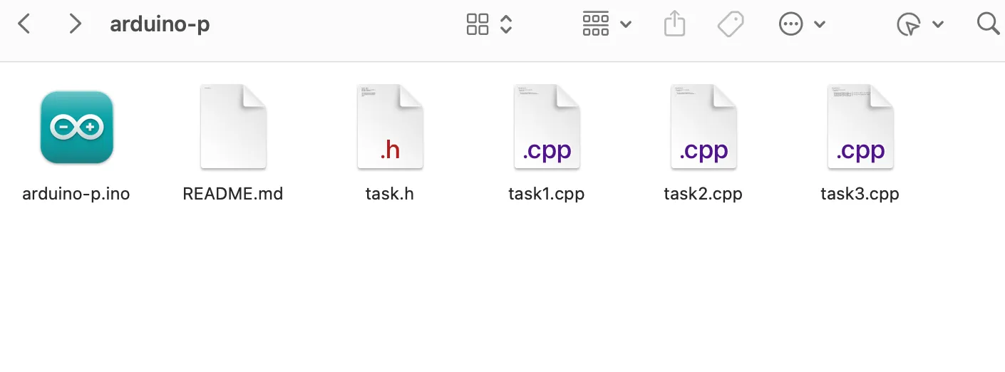
task.h
C++#ifndef TASK_H
#define TASK_H
#include <Arduino_FreeRTOS.h>
#include "Arduino.h"

void taskPrint1(void *param);
void taskPrint2(void *param);
void taskBlink(void *param);
#endif
task1.cpp
C++#include"task.h"

void taskPrint1(void *param){
  while (1)
  {
    Serial.println("taskPrint1...");
    vTaskDelay(1000 / portTICK_PERIOD_MS );
  }
}
task2.cpp
C++#include"task.h"

void taskPrint2(void *param){
    while (1)
  {
    Serial.println("taskPrint2...");
    vTaskDelay(1000 / portTICK_PERIOD_MS );
  }
}
task3.cpp
C++#include"task.h"

void taskBlink(void *param){
    while (1)
  {
    digitalWrite(LED_BUILTIN, HIGH);  // turn the LED on (HIGH is the voltage level)
    vTaskDelay(1000 / portTICK_PERIOD_MS );
    digitalWrite(LED_BUILTIN, LOW);   // turn the LED off by making the voltage LOW
    vTaskDelay(1000 / portTICK_PERIOD_MS );
  }

}
最后修改.ino文件
C++/*
  Blink

  Turns an LED on for one second, then off for one second, repeatedly.

  Most Arduinos have an on-board LED you can control. On the UNO, MEGA and ZERO
  it is attached to digital pin 13, on MKR1000 on pin 6. LED_BUILTIN is set to
  the correct LED pin independent of which board is used.
  If you want to know what pin the on-board LED is connected to on your Arduino
  model, check the Technical Specs of your board at:
  https://www.arduino.cc/en/Main/Products

  modified 8 May 2014
  by Scott Fitzgerald
  modified 2 Sep 2016
  by Arturo Guadalupi
  modified 8 Sep 2016
  by Colby Newman

  This example code is in the public domain.

  https://www.arduino.cc/en/Tutorial/BuiltInExamples/Blink
*/


#include "task.h"

// the setup function runs once when you press reset or power the board
void setup() {
  Serial.begin(115200);           // Initialize serial communication at a baud rate of 115200
  // initialize digital pin LED_BUILTIN as an output.
  pinMode(LED_BUILTIN, OUTPUT);
  // Create task
  xTaskCreate(taskPrint1, "Print1", 128, NULL, 1, NULL);
  xTaskCreate(taskPrint2, "Print2", 128, NULL, 2, NULL);
  xTaskCreate(taskBlink, "Blink", 128, NULL, 3, NULL);
  vTaskStartScheduler();
}

// the loop function runs over and over again forever
void loop() {

}
再次编译,烧录,打开串口监视器看到程序正常运行。 但是,这样看起来,文件多了,还是会混乱,那有没有更好的方法,创建目录来管理? 可以,但是必须要用src目录与.ino文件同级,子目录或者子文件再放进src。 官方给出的回答:https://arduino.stackexchange.com/questions/54651/arduino-ide-and-subfolders
多目录管理 先新建一个src目录,把文件再进来:
shell.
├── README.md
├── arduino-p.ino
└── src
    ├── task.h
    ├── task1.cpp
    ├── task2.cpp
    └── task3.cpp
注意修改.ino的导入头文件#include "src/task.h"
本文作者:phae
本文链接:
版权声明:本博客所有文章除特别声明外,均采用 BY-NC-SA 许可协议。转载请注明出处!